
Micro Vias
As the demand for lightweight, portable devices with more functionality increases, electronics designers seek to maximize their input/output (I/O) density in smaller footprint areas. This drives the development of high-density interconnect (HDI) substrates and printed circuit boards (PCBs) with finer traces, less space between layers, and smaller vias. Microvias have facilitated this evolution by providing an effective interconnect alternative to conventional through-holes.
Microvias are drilled into the micro vias layers using various methods, including mechanical drilling and laser drilling. The precise manipulation of these tools is necessary to guarantee that the holes have the correct size and shape. They are then filled with conductive material, typically copper, to provide an electrical connection between the layers of the PCB. This process is accompanied by specialized plating techniques that ensure the copper adheres correctly to the via walls.
The materials used to construct microvias play a critical role in their reliability and performance, including the drilling and plating processes themselves, as well as the substrate and inner copper layer composition. Conductive copper is the most commonly utilized material, chosen for its excellent electrical properties and thermal stability. The choice of an appropriate epoxy resin and copper thickness is also vital for both the drilling and metallization processes. These factors must be balanced to achieve optimal results without compromising the integrity of the final product.
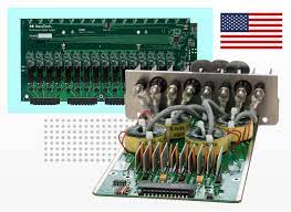
Materials Used in Micro Vias
Stacked microvias are a popular design strategy for high-speed digital and radiofrequency (RF) circuitry because they provide a shorter, more direct path for signals to travel between the different layers. This reduces parasitic inductance and capacitance, which can degrade signal integrity. In addition, stacked microvias allow a higher density of signals to be accommodated on the same PCB, reducing overall system power consumption.
As with other types of through-holes, buried and blind microvias are available in different designs. Stacking them allows you to use space more efficiently and can be easier to assemble, but it can make the vias more vulnerable to thermal stress during solder reflow and operation.
On the other hand, staggering your buried and blind vias can be more reliable. However, they require more time to drill and more complicated layouts are needed to create them. In either case, these structures can lead to microvia failure ICDs if the drilling and metallization processes are not performed with care.
As the technology behind PCBs continues to evolve, ensuring that microvias are constructed and plated correctly is crucial for optimum reliability. This requires a thorough quality control process, from inspection of the raw materials to the verification of the dimensions and specifications at every step of production. To meet these requirements, manufacturers must adhere to strict standards and rigorous test protocols. Failure to comply with these standards can lead to interconnect defects that manifest as open circuits, intermittent problems at high temperatures, or even circuit failures.

